Why Rendering a Triangle is Complicated
Last week, my dad was asking me why I was proud of this triangle on
my laptop.

I told him that rendering a triangle is complicated: it took me 3
days, and 1000+ lines of code to create the above image. This just made
him more confused.
So I wrote this article explaining what the Vulkan graphics API is,
how it works, and everything that goes into rendering a triangle with
your GPU.
What Vulkan Is
Vulkan is a graphics API that is designed to provide an accurate
abstraction of how modern graphics processing units (GPUs) work. Unlike
OpenGL, Vulkan is very verbose. Every detail related to the graphics API
needs to be set up from scratch. The upsides to this are that you only
use what you choose to, and you can better understand what's going on in
your application and in doing so achieve much higher performance.
This article is intended to be a concise overview of the fundamentals
of Vulkan. It was written for somebody who knew Vulkan but has forgotten
many of the details (i.e. future me). Most of the information here comes
from the Vulkan
1.2 Spec.
Note: This article uses the C++ bindings for
Vulkan
Vulkan in a Nutshell
From a bird's eye view, here's how a Vulkan application
works:
Vulkan can access devices, which let you control one
or more queues. Queues are how you send a list of
commands to the GPU, and they can be members of one or more
queue families, each of which can do different things
(e.g. draw the vertices of a 3D model).
Command buffers are how you submit commands to a
queue. Device commands are 'recorded' to a command buffer through Vulkan
API calls, and can then be submitted once or many times (e.g. once every
frame) to a queue to be executed.
That's the TL;DR - now it's time to dive into the details!
Genesis
Instances and Devices
In the beginning there was the Vulkan API. And the API was made
flesh through vk::Instance, and from it sprung all
per-application state.
You initialize Vulkan by creating an instance, which contains
application state - information like what version of the Vulkan API
you're using, your application's name, and which extensions and layers
you want to enable. Extensions and layers provide behavior that isn't
included by default in Vulkan, like extended error checking and call
logging.
With an instance you can examine the physical
devices (usually GPUs) that are available. A machine might have
multiple physical devices, and each of their properties (such as being a
dedicated graphics card) can be inspected.
A common pattern for physical device selection is to:
- List all of the physical devices
- Score each physical device on desired properties
- Give physical devices without required properties a score of 0
- Pick the physical device with the highest score
Example code for physical device selection
(Tip: Read the comments so you don't get overwhelmed by code)
void pickPhysicalDevice() {
  // Get list of all physical devices that can be found by Vulkan
  auto physicalDevices = instance.enumeratePhysicalDevices();

  if (physicalDevices.size() == 0) {
    throw std::runtime_error("No GPUs with Vulkan support found!");
  }

  // Create list of physical devices sorted by rateDeviceSuitability
  std::multimap<int, vk::PhysicalDevice> candidates;

  for (const auto& physicalDevice : physicalDevices) {
    int score = rateDeviceSuitability(physicalDevice);
    candidates.insert(std::make_pair(score, physicalDevice));
  }

  // Check if best candidate meets required properties (score > 0)
  if (candidates.rbegin()->first > 0) {
    physicalDevice = candidates.rbegin()->second;
  } else {
    throw std::runtime_error("failed to find a suitable GPU!");
  }
}

int rateDeviceSuitability(vk::PhysicalDevice physicalDevice) {
  // Get all features / properties of a given physical device
  vk::PhysicalDeviceFeatures deviceFeatures
    = physicalDevice.getFeatures();

  vk::PhysicalDeviceProperties deviceProperties
    = physicalDevice.getProperties();

  int score = 0;

  if (   deviceProperties.deviceType
      == vk::PhysicalDeviceType::eDiscreteGpu)
  {
    score += 1000;  // Prefer dedicated GPUs
  }

  if (!deviceFeatures.geometryShader) {
    return 0;       // Require geometry shaders
  }

  return score;
}
With a physical device you can create a logical
device.
A logical device is basically a physical device (which represents a
GPU) that is initialized and ready for work. They're what you use to
create resources and queues.
Making Stuff Happen
Queues, Command Buffers, and Render
Passes
A queue is a list of commands that the GPU executes.
Each queue can only have certain types of commands (some can have
multiple types, others just one), and this is specified when a queue is
created.
The four types of queue operations are:
- Graphics ---> Drawing the vertices of a
model
- Compute ---> Ray tracing, cloth simulation
- Transfer ---> Loading textures and buffers
- Sparse ---> Loading part of a
'mega-texture'
A physical device will give you access to several queues of different
queue families, and when you create a queue it will be
an index to a queue of a matching queue family on the device. Queue
families are queues that have the same properties as one another (e.g.
perform both graphics and compute operations).
Commands are submitted to queues by first recording a series of
commands into a command buffer and then submitting the entire command
buffer to a queue with vk::Queue::submit().
Note: Command buffers are usually re-recorded every frame (and not
reused) to account for the change in workload in an application (e.g.
drawing a new 3D model after an event).
Also, you can submit multiple command buffers to a single queue. This
is useful because it can allow you to ensure that one set of
commands from a command buffer completes execution before another
command buffer in the queue starts (more on this later), and it allows
you to take advantage of multi-core CPUs by recording each of the
command buffers in parallel on multiple threads.
Finally, commands recorded in command buffers can perform:
- Actions ---> draw, dispatch, clear, copy, query
operations etc
- State setting ---> bind pipelines / buffers,
push constants etc
- Synchronization ---> set / wait events, pipeline
barriers etc
Some commands perform just one of these tasks, while others do
several. A render pass is needed to execute certain
commands, including drawing.
Render Passes
A render pass consists of one or more subpasses,
along with several framebuffers. Framebuffers represent
a series of memory attachments (e.g. color, depth etc) that each subpass
can read from and write to.
A command in a subpass might write to a color buffer, which will
allow for later subpasses / render passes to read from it. This allows
for techniques like deferred rendering.
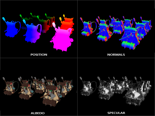
Deferred rendering is a story for another day, but the gist of it is
that you can store most of the geometry information in an initial render
pass, and defer expensive rendering operations like lighting
for later.
Example code for recording to a command buffer and render pass
// Create a command buffer
vk::CommandBuffer cmd;

// Start recording to the command buffer and render pass
cmd.begin(vk::CommandBufferBeginInfo());
cmd.beginRenderPass(vk::RenderPassBeginInfo());

// Bind a graphics pipeline (covered later)
cmd.bindPipeline(vk::PipelineBindPoint::eGraphics, graphicsPipeline);

// Bind vertex buffers containing info needed to draw vertices
cmd.bindVertexBuffers(0, 1, vertexBuffers, offsets);

// Draw the buffer currently bound to this command buffer
cmd.draw(vertices.size(), 1, 0, 0);

// Stop recording to the render pass and command buffer
cmd.endRenderPass();
cmd.end();
Last thing! Some commands that perform actions (e.g. draw vertices)
do so based on the current state (e.g. the currently bound array of
vertices) set by commands since the start of the command buffer. This
means that in the above code example, cmd.draw() will
operate on the current state set by cmd.bindVertex() in the
previous line. This "synchronization guarantee", that one command will
finish executing before the next one starts, is usually not true.
Synchronization
GPUs are optimized for operation throughput, and because of this
(with a few exceptions) commands are not executed in the
order they were recorded in. The first command that
performs an action in a command buffer isn't guaranteed to finish
executing before the last action command in that buffer. The first
command buffer submitted to a queue won't necessarily finish any
commands before a later command buffer starts. The same thing applies to
command buffers submitted on different queues and multiple
subpasses.
At places the Vulkan spec is confusing on this topic, but the TL;DR
is that this is true unless a synchronization object is
used (or with state setting commands within a single command
buffer).
There are a few different types of synchronization objects:
Fences (GPU to CPU sync) ---> EX: ensure
there are only two rendered frames at a time in the swap chain (i.e.
double buffering)
Semaphores (GPU to GPU sync across queues)
---> EX: wait for frame to finish rendering before presenting
it
Barriers (Sync within a command buffer /
pipeline) --> EX: start compute shader execution as soon as the
vertex shader is finished
Subpass Dependencies (Sync between subpasses)
--> EX: wait for the normal and albedo attachments to complete before
starting the lighting rendering subpass.
Synchronization is closely tied to the graphics
pipeline.
The Graphics Pipeline
The graphics pipeline is what takes the meshes and textures of 3D
models (along with other information) and turns them into pixels on your
2D screen. Each stage of the graphics pipeline operates on the output of
the previous stage.
There are two types of stages in the graphics pipeline:
fixed-functions and shaders.
Fixed-functions complete operations that can be
tweaked with parameters, but the way they work is predefined. Anything
in the graphics pipeline that isn't a shader is a fixed function.
Shaders are user-created programs that execute in
the graphics pipeline. They can read from input variables (e.g. position
of vertex / fragment / light) and run on GPUs, which are great at
parallel computing tasks such as applying the same lighting rule for
every one of the 2 million pixels on your screen or rotating a 3D model
with thousands of vertices.

A simplified overview of the graphics pipeline consists of 7
stages:
Input Assembler: Collects the raw vertex data
from specified buffers. Optionally, an index buffer can be used to
repeat certain elements without duplicating vertex data.
Vertex Shader: Runs on every vertex and passes
per-vertex data down the graphics pipeline. Usually applies
transformations to vertices, and converts from model space to screen
space.
Tessellation: Optional. Runs on arrays of
vertices ("patches") and subdivides them into smaller
primitives.
Geometry Shader: Optional. Runs on every
primitive (triangle, line, point) and can discard or output more
primitives. This stage is often not used because its performance isn't
great on most graphics cards.
Rasterization: Discretizes the primitives into
fragments (the data necessary to generate a pixel). Fragments that fall
outside the screen and fragments that are behind other primitives are
discarded.
Fragment Shader: Runs on every fragment and
determines its color, depth value, and which framebuffer the fragment is
written to. Often uses interpolated data from the vertex shader such as
surface normals to apply lighting.
Color Blending: Applies operations to mix
different fragments that map to the same pixel in the framebuffer.
Fragments can overwrite each other, or be mixed based on
transparency.
Shader Modules
Unlike OpenGL, shader code in Vulkan has to be in a bytecode format
called SPIR-V, as opposed to human-readable syntax like GLSL.
The advantage of using a bytecode format is that the compilers to
turn shader code into native GPU code are significantly less complex.
This leads to SPIR-V shader code being more reliable across GPU
vendors.
However, shaders are still commonly written in GLSL, and later
compiled to SPIR-V using a tool called glslc (included in
the Vulkan SDK). SPIR-V can be passed to the graphics pipeline by
reading the bytecode, and then wrapping it in a
vk::ShaderModule object, which specifies the entry point
function in the shader, and assigning it to a specific stage of the
graphics.
Presentation Time
Swap Chains and Window Surfaces
We've done all of this work to render an image, now we need to
present that image to a window surface from the
swap chain.
A window surface allows you to interact with platform specific
display systems.
A swap chain is an array of at least two presentable images. The
first image is the screenbuffer, which is the image presented to the
screen, and later images are backbuffers. If you don't use a backbuffer
and directly send new images to the screenbuffer, image tearing (where
the top portion of the screen contains the new image and the bottom
portion contains the old image) will occur while the monitor is
refreshing.
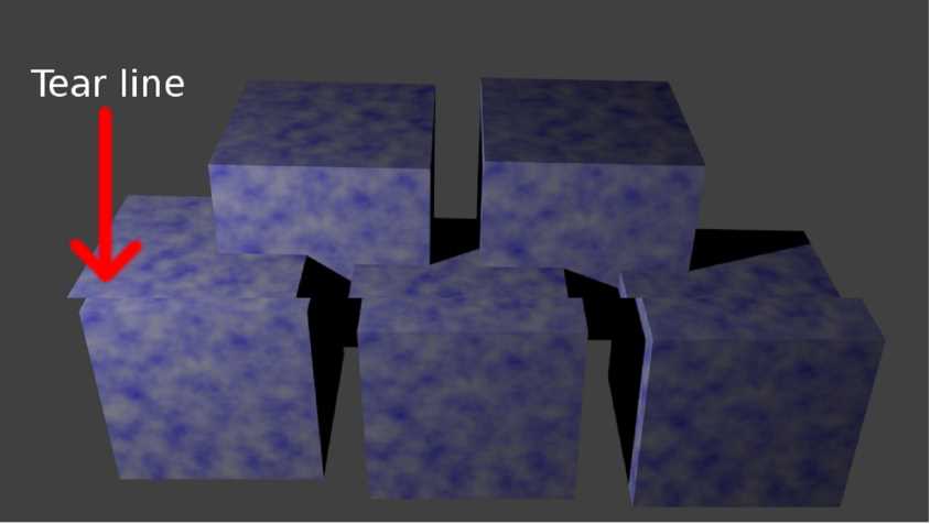
Using a screenbuffer and a single backbuffer is known as a double
buffer. This technique prevents image tearing.
Rendering a Triangle
To bring it all together, in a Vulkan application:
We start by creating an instance, a physical device, and a
logical device.
Commands are recorded in command buffers and render passes, which
are submitted to queues. The GPU goes through the queues and executes
the commands in them
To guarantee that certain commands occur after other commands
finish executing, synchronization objects have to be used.
Some commands are involved with stages in the graphics pipeline,
which can either be shaders or fixed functions, and turns 3D data into a
2D image
Finally, the window surface presents images from a swap chain to
the screen
That's why rendering a triangle is complicated.
Feel free to contact me on Twitter. Feedback and
comments are appreciated :)